- 技术(专利)类型 实用新型
- 申请号/专利号 201521043917.6
- 技术(专利)名称 一种分体拉线开关
- 项目单位
- 发明人 徐吉春
- 行业类别 人类生活必需品
- 技术成熟度 详情咨询
- 交易价格 ¥面议
- 联系人 徐吉春
- 发布时间 2022-12-20
 北京
北京
客服热线:010-83278899
 微信公众号 扫一扫 关注我们


项目简介
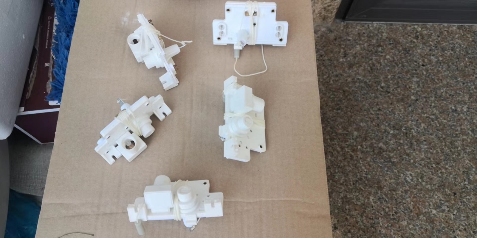
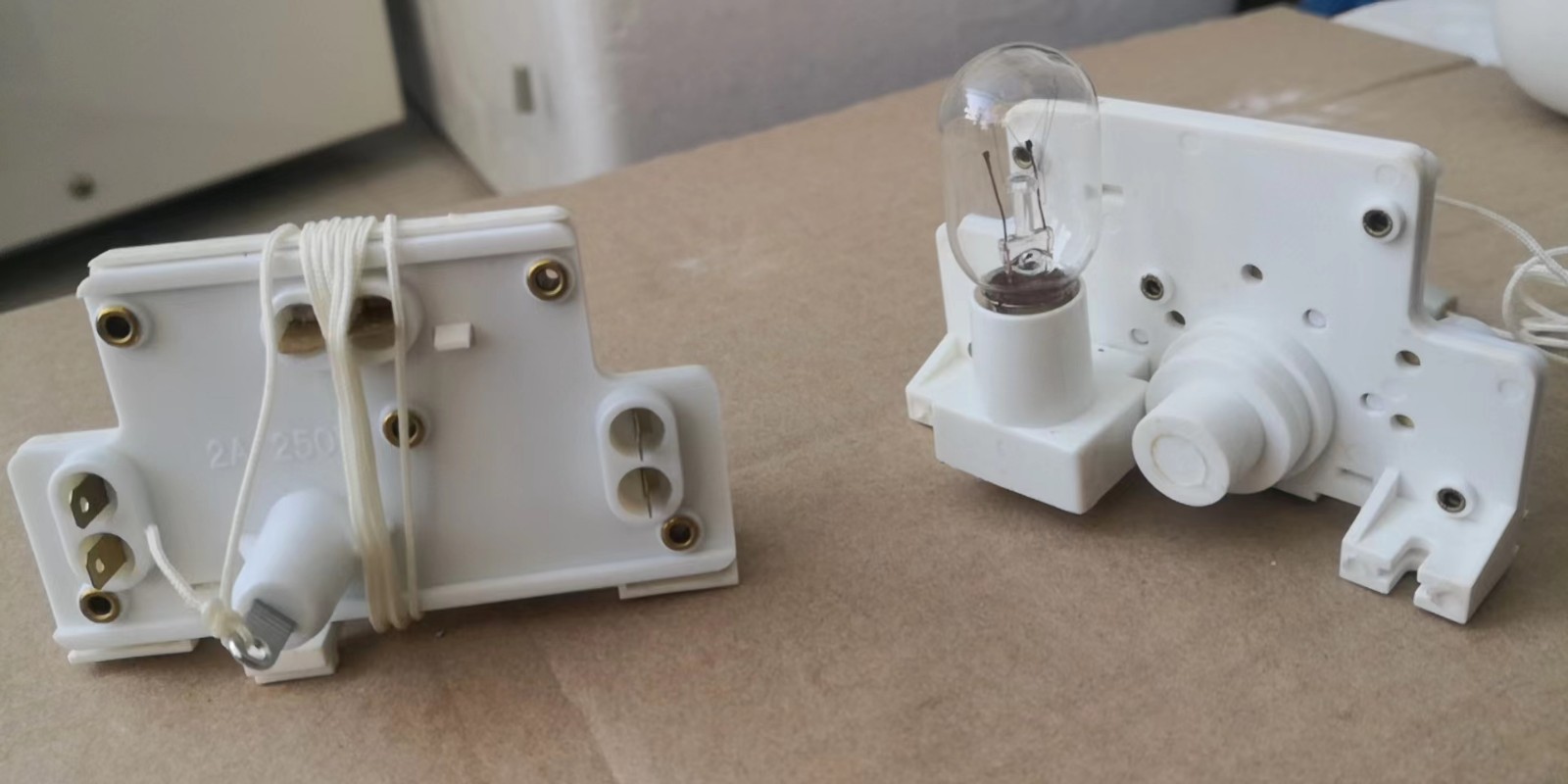
本实用新型公开了一种分体拉线开关,包括:外壳;铜片电路,其设于所述外壳内部;开关组件,其设于所述壳内部,且所述开关组件可导通或断开所述铜片电路。本实用新型的拉线开关的可同时操作多个灯泡,结构小巧禁紧凑,且使用方便。
说明书
技术领域
[0001]本实用新型涉及电网配件,尤其涉及拉线开关。
背景技术
[0002]拉线开关一般用于小功率电器的控制,如照明电灯等。拉线开关在使用时,操作人员通过拉动绝缘线控制开关内的转轴转动,从而实现电路的接通或断开;拉线开关由于采用绝缘线控制开关内的部件动作,有效地拉长了带电部件与操作人员的距离,使用时更加安全。
[0003]现有技术的拉线开关结构简单,无法控制多台照明电灯,当需要控制多台电灯时,需要增加多台开关,即增加了成本又减弱了使用的便捷度。
实用新型内容
[0004]本实用新型的目的是提供一种分体拉线开关,且其采用以下技术方案:
[0005] —种分体拉线开关,包括:
[0006]外壳;
[0007]铜片电路,其设于所述外壳内部;
[0008]开关组件,其设于所述壳内部,且所述开关组件可导通或断开所述铜片电路。
[0009]所述开关组件包括:第一弹簧;
[0010]旋转轮;其包括一筒状的固定部及设于所述固定部一侧的限位部,且所述限位部包括若干锯齿凸起,所述固定部内侧设有一固定通孔;
[0011]拉杆,其包括一动力部及一拉动部,且所述动力部为所述拉动部的末端扭转形成,所述拉动部上设有限位凸起,所述拉动部穿过所述固定通孔,且所述拉动部一侧通过限位凸起限位,所述第一弹簧套设于所述动力部上,所述第一弹簧两端分别通过所述动力部的底部及所述旋转轮限位;
[0012]导电片,其包括导电片主体,且所述导电片主体套设于所述旋转轮的固定部外侧,且所述导电片主体上连接导电触片,且所述导电片主体上设有若干第一转动凸起,所述第一转动凸起可与所述锯齿凸起卡扣,且所述第一转动凸起只能相对于所述锯齿凸起一个方向转动。
[0013]还包括一第二弹簧,所述第二弹簧套设于所述固定部上,所述第二弹簧与所述导电片接触且电性连接,且所述第二弹簧的两端分别通过所述导电片及所述外壳限位。
[0014]所述导电触片一端与所述导电片主体连接,且所述导电片主体的另一端向远离所述导电片主体方向弯折。
[0015]所述铜片电路包括:
[0016]第一铜线,其设有若干第一连接端;
[0017]第二铜线,其与所述第二弹簧电性连接;
[0018]若干第三铜线,且所述第三铜线一端设有一第二连接端,且所述第三铜线的另一端可与所述导电触片电性连接。
[0019]所述外壳上还包括若干第二转动凸起,且所述第二转动凸起可与所述导电触片卡扣,且所述第二转动凸起只能相对于所述导电触片一个方向转动。
[0020] 所述外壳包括一上盖及一下盖,且所述上盖及所述下盖可固定一体内部形成一容置空腔。
[0021 ] 还包括一固定座,其与所述外壳可拆卸且电性连接,且所述固定座可连接一灯泡。
[0022]所述灯泡与所述固定座的连接方向与所述外壳平行。
[0023]本实用新型的优点是:本实用新型的拉线开关的可同时操作多个灯泡,结构小巧紧凑,且使用方便。
发明内容
Utility model content
The purpose of this utility model is to provide a kind of split pullswitch, and it is by the following technical solutions:
A kind of split pullswitch, comprising:
Shell;
Copper sheet circuit, it is located at described enclosure;
Switch module, it is located at described shell inside, and described switch module can conducting or disconnect described copper sheet circuit.
Described switch module comprises: the first spring;
Swiveling wheel; It comprises the fixed part of a tubular and is located at the limiting section of described fixed part one side, and if described limiting section compriseDry serrate projections, described fixed part inner side is provided with a fixed via;
Pull bar, it comprises a power part and a pulling department, and the described power part end that is described pulling department reverses and form, described inPulling department is provided with spacing preiection, and described pulling department is through described fixed via, and described pulling department one side is limit by spacing preiectionPosition, described the first spring housing is located on described power part, and described the first both ends of the spring is respectively by bottom and the institute of described power partState swiveling wheel spacing;
Conducting strip, it comprises conducting strip main body, and described conducting strip main body is sheathed on the fixed part outside of described swiveling wheel, and instituteState in conducting strip main body and connect conductive contact blade, and described conducting strip main body is provided with some the first pivot protrusion, described the first rotationProjection can with described serrate projections buckle, and described the first pivot protrusion can only be rotated with respect to direction of described serrate projections.
Also comprise one second spring, described the second spring housing is located on described fixed part, and described the second spring and described conducting strip connectTouch and be electrically connected, and the two ends of described the second spring are spacing by described conducting strip and described shell respectively.
Described conductive contact blade one end is connected with described conducting strip main body, and the other end of described conducting strip main body is to away from described conductionThe bending of sheet main direction.
Described copper sheet circuit comprises:
The first copper cash, it is provided with some the first links;
The second copper cash, itself and described the second spring are electrically connected;
Some the 3rd copper cash, and described the 3rd copper cash one end is provided with one second link, and the other end of described the 3rd copper cash can be withDescribed conductive contact blade is electrically connected.
On described shell, also comprise some the second pivot protrusion, and described the second pivot protrusion can with described conductive contact blade buckle, andDescribed the second pivot protrusion can only be rotated with respect to direction of described conductive contact blade.
Described shell comprises a upper cover and a lower cover, and described upper cover and the described lower cover inner accommodating cavity that forms that can be fixed as one.
Also comprise a holder, itself and described shell are detachable and be electrically connected, and described holder can connect a bulb.
Described bulb is parallel with described shell with the closure of described holder.
The utility model has the advantages that: pullswitch of the present utility model can operate multiple bulbs simultaneously, structure compact,And easy to use.
附图说明null实施方式
[0030]下面结合附图进一步阐述本实用新型的具体实施方式:
[0031]如图1至图5所示,本实用新型公开了一种分体拉线开关,包括:外壳1、铜片电路2及开关组件3,铜片电路2设于所述外壳2内部;开关组件3设于所述壳I内部,且所述开关组件3可导通或断开所述铜片电路2。
[0032]本实用新型通过外壳中间设置安装铜片电路,且通过开关组件控制铜片电路的导通或断开,灯座与固定座结合固定;开关采用拉杆式可多位控制载体;适用于各种灯具。
[0033]本实用新型的开关组件2包括第一弹簧31、旋转轮32、拉杆33、导电片34和第二弹簧35。旋转轮32包括一筒状的固定部321及设于所述固定部321—侧的限位部322,且所述限位部322包括若干锯齿凸起,所述固定部内侧设有一固定通孔。拉杆33包括一动力部333及一拉动部331,且所述动力部333为所述拉动部331的末端扭转形成,所述拉动部331上设有限位凸起332,所述拉动部331穿过所述固定通孔,且所述拉动部331—侧通过限位凸起332限位,所述第一弹簧31套设于所述动力部333上,所述第一弹簧31两端分别通过所述动力部333的底部及所述旋转轮32限位.导电片34包括导电片主体,且所述导电片主体套设于所述旋转轮的固定部外侧,且所述导电片主体上连接导电触片,且所述导电片主体上设有若干第一转动凸起,所述第一转动凸起可与所述锯齿凸起卡扣,且所述第一转动凸起只能相对于所述锯齿凸起一个方向转动,所述导电触片一端与所述导电片主体连接,且所述导电触片的另一端向远离所述导电片主体方向弯折,所述外壳上还包括若干第二转动凸起(图中未示出),且所述第二转动凸起可与所述导电触片卡扣,且所述第二转动凸起只能相对于所述导电触片一个方向转动。
[0034]第二弹簧套34设于所述固定部上,所述第二弹簧与所述导电片接触且电性连接,且所述第二弹簧的两端分别通过所述导电片及所述外壳限位。
[0035]本实用新型的铜片电路包括:第一铜线、第二铜线和若干第三铜线,第一铜线设有若干第一连接端21;第二铜线与所述第二弹簧电性连接;所述第三铜线一端设有一第二连接端22,且所述第三铜线的另一端可与所述导电触片电性连接,第一连接端和第二连接端分别连接电路的火线及零线。
[0036] 本实用新型的外壳包括一下盖11及一上盖12,且所述上盖12及所述下盖11可固定一体内部形成一容置空腔,通过该容置空腔容置固定所述的铜片电路2和开关组件3。
[0037]本实用新型的工作原理为:
[0038] 通过拉动拉杆的拉动部,可带动动力部运动,由于动力部为拉动部扭曲形成,因此动力部在向前运动的过程中,带动旋动轮向前运动并同时转动,由于旋转轮上设有锯齿凸起,且该锯齿凸起与导电片上设有的第一转动凸起卡扣,因此旋转轮在转动的过程中带动导电片转动,导电片在转动时,导电触片可与所述第三铜线的另一端电性连接,此过程中旋转轮与导电片卡扣不能相对运动,且导电片相对于外壳可以转动。当施加于拉杆的拉动部上外力消失后,由于第二弹簧的作用,拉杆会退回,退回的过程中会带动旋转轮向后退同时转动,此时导电片相对于外壳不能转动,且旋转轮可对于导电片发生转动。当拉动杆在外力的作用下前后往复运动的过程中,导电片完成与第三导线的第二端电性连接或断开,从而完成开关的导通或断开。
[0039]本实用新型中,第三电线设有三条,因此本开关可同时控制三个电灯,
[0040] 本实用新型还包括一固定座4,其与所述外壳可拆卸且电性连接,且所述固定座可连接一灯泡。所述灯泡与所述固定座的连接方向与所述外壳平行。由于本实用新型的开关在固定时外壳与墙面水平固定,因此固定好的开关上的固定座与墙面平行,当固定座上安装有灯泡时,灯泡的照射范围最大。
[0041]以上所述仅为本实用新型的较佳实施例而已,并不用以限制本实用新型,凡在本实用新型的精神和原则之内所作的任何修改、等同替换和改进等,均应包含在本实用新型的保护范围之内。


企业营业执照
专利注册证原件
身份证
个体户营业执照
身份证
专利注册证原件
专利代理委托书
转让申请书
转让协议
手续合格通知书
专利证书
专利利登记簿副本


提交